Besonderheit:
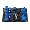
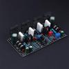
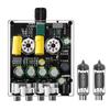
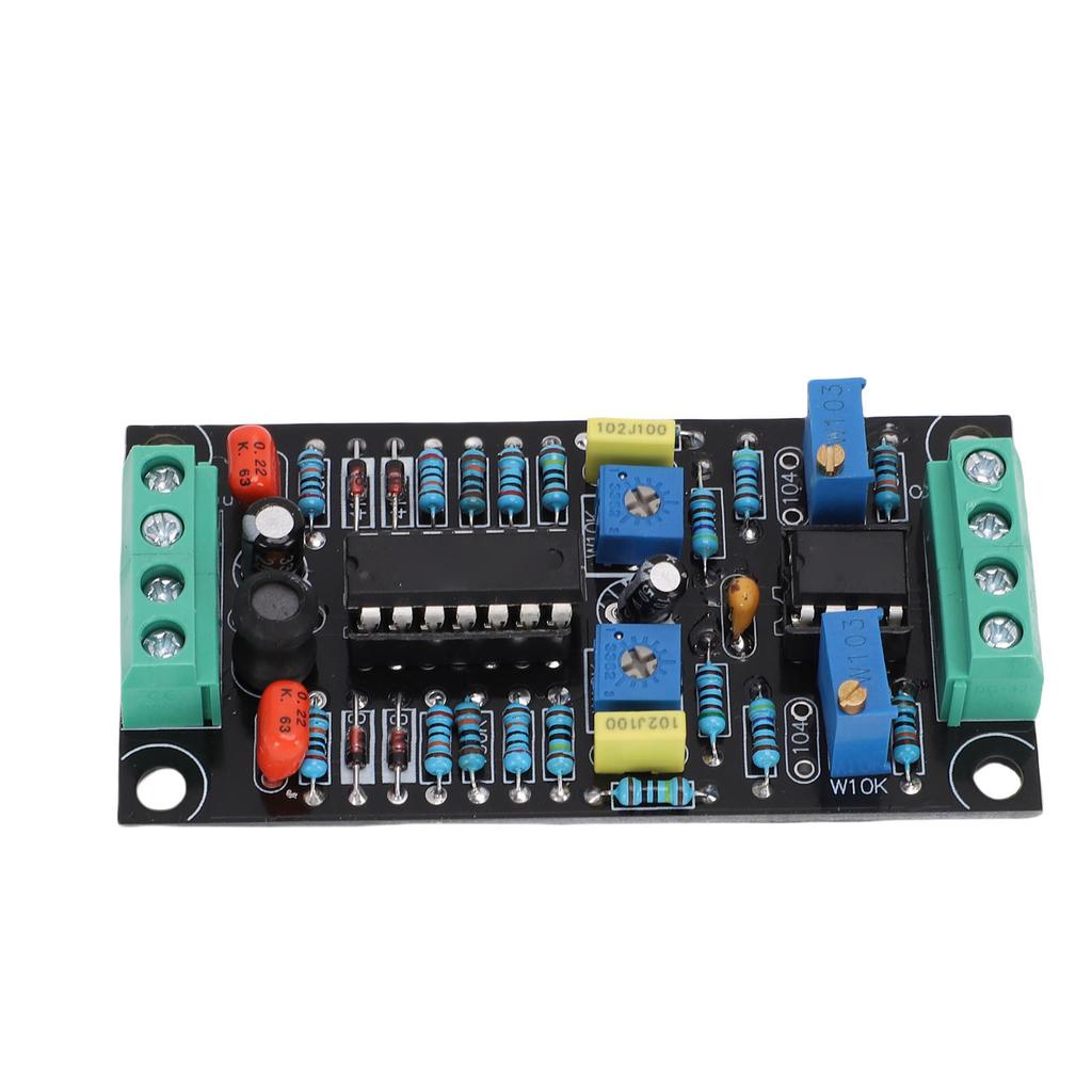
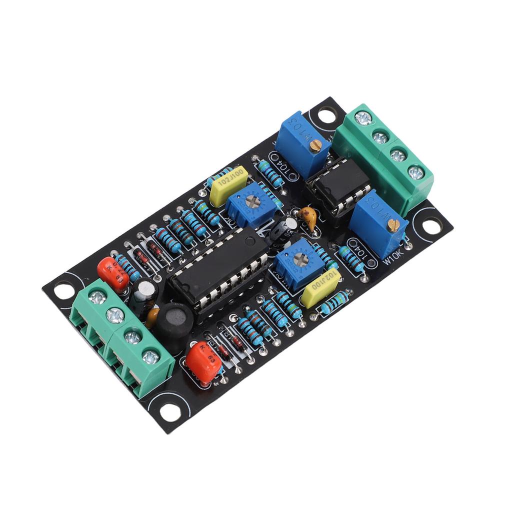
1. VU Meter Treiberplatine: Diese VU-Pegelmesser-Treiberplatine verwendet LMC660- und LM358-Chips, was eine zuverlässige Leistung gewährleistet und sich gut als Audiozubehör eignet.
2. Energieeffizient: Die VU-Meter-Treiberplatine verfügt über ein Design mit geringem Stromverbrauch und verbraucht weniger als 10 mA, was sie zu einer effizienten Wahl für Audioanwendungen macht.
3. 500uA Vollausschlag-Design: Dieses VU-Meter-Treiber-Modul verwendet ein Vollbereichsdesign von 500 µA und ist mit den meisten Lautstärkemessern kompatibel, geeignet für verschiedene Audiosysteme.
4. Zweikanal-Treiber: Die VU-Meter-Treiberplatine verwendet ein zweikanaliges Treiberdesign, das es ermöglicht, mit einer einzigen Platine linke und rechte Kanal-Lautstärkemesser anzusteuern.
5. Einfache Bedienung: Diese DB-Pegelmesser-Treiberplatine kann die Einstellzeit verkürzen, die Wiederholgenauigkeit verbessern und eine einfache Bedienung für jedermann gewährleisten.
Spezifikation:
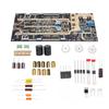
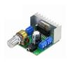
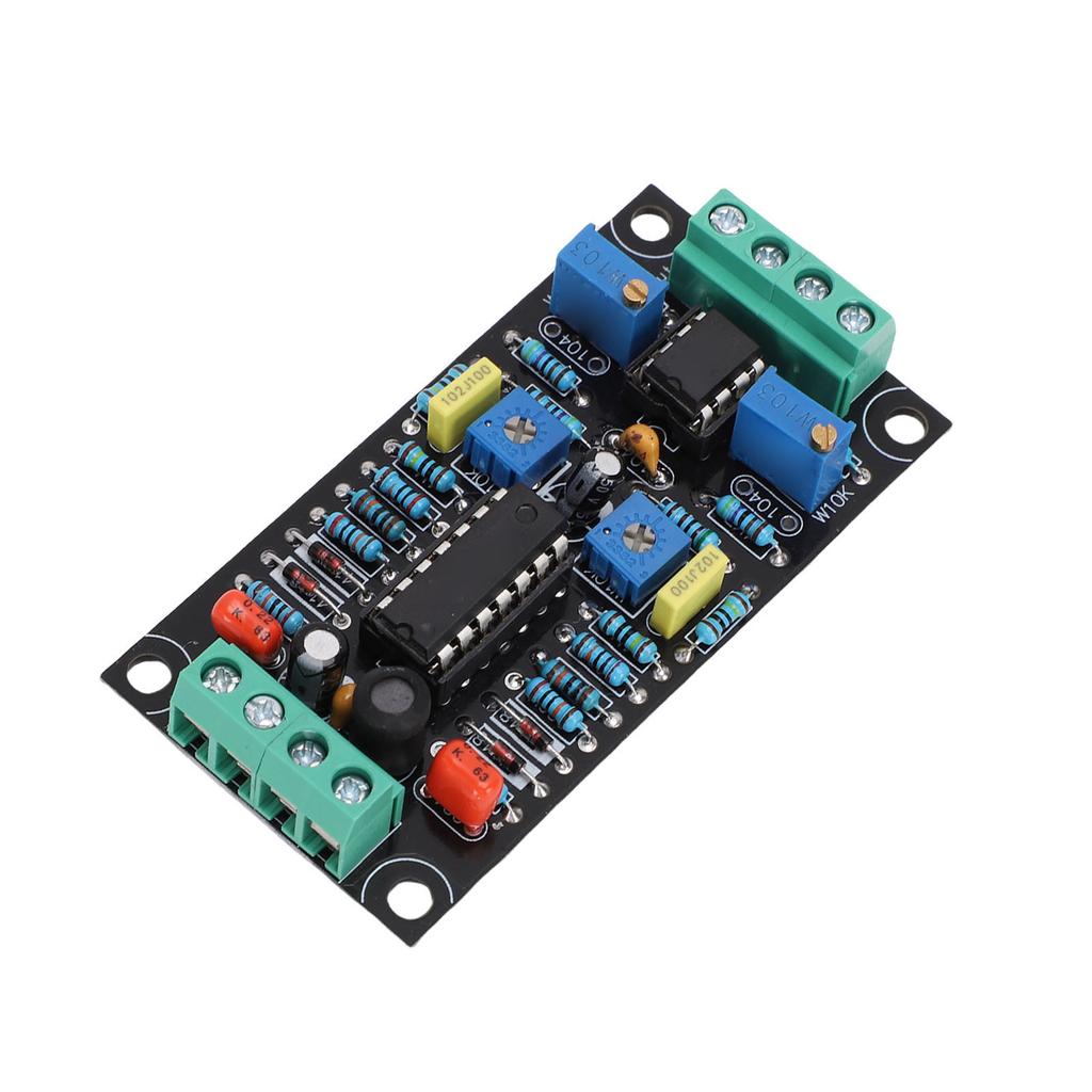
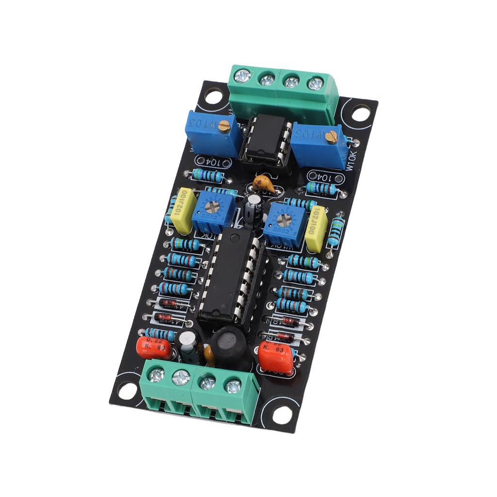
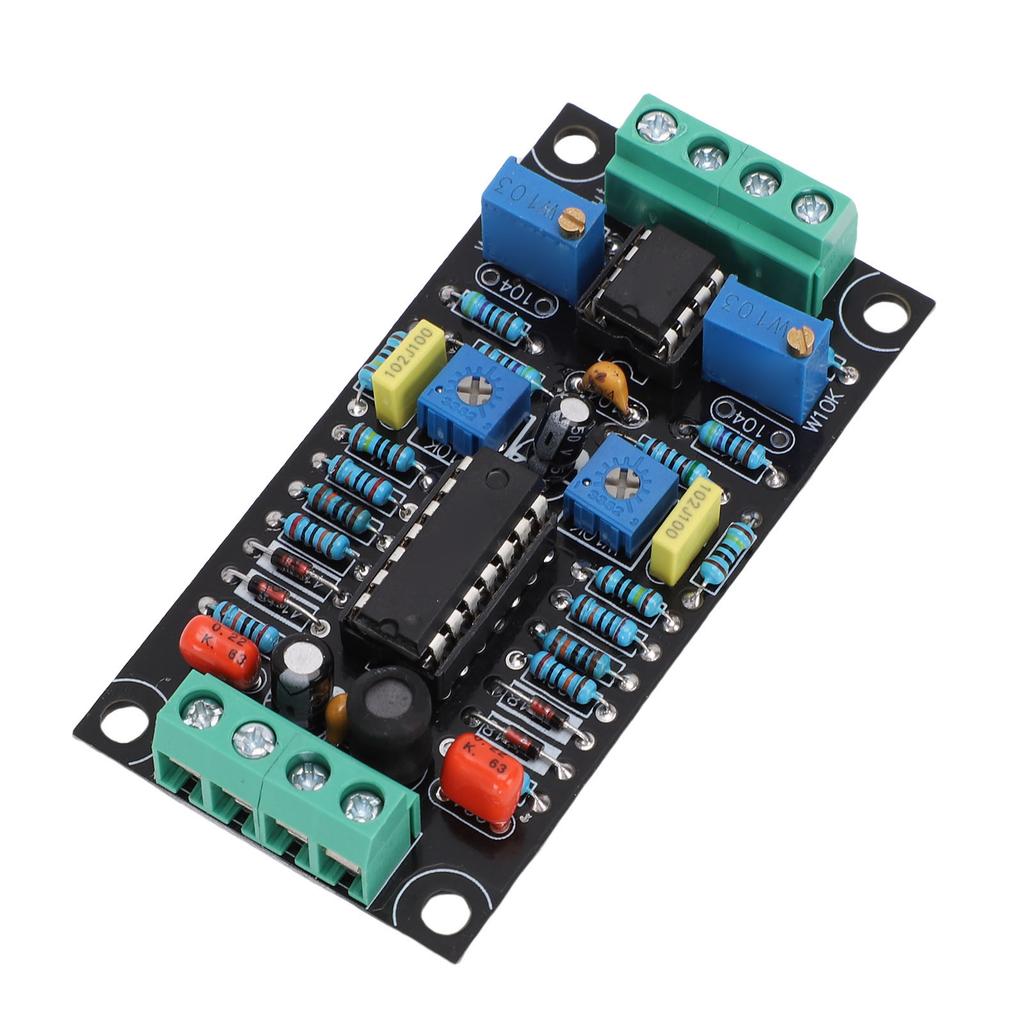
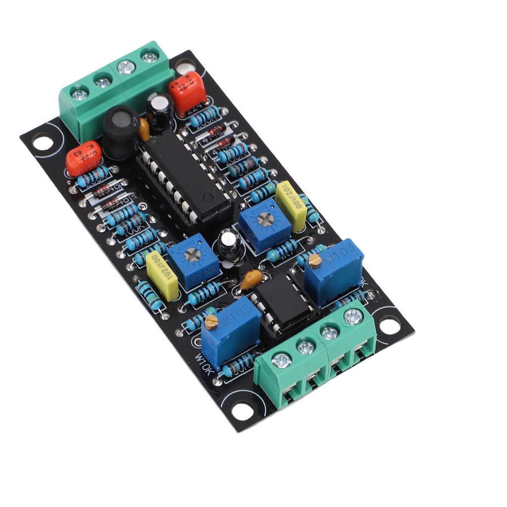
Gegenstandsart: VU Meter Treiberplatine
Material: PCB
Produktgröße: Ca.. 73,5x37,5mm 2,89x1,48in
Größe der Installationsbohrung: Ca.. 66x31mm 2.60x1.22in
Beschreibung der Funktion:
1. Gespeist von einer einzelnen Stromversorgung.
2. Reduzieren Sie die Einstellzeit, verbessern Sie die Wiederholgenauigkeit, gewährleisten Sie eine einfache Bedienung für jeden.
3. Bei Verwendung einer Sinuswelle von 0 Veff misst das VU-Meter 1 dB.
4. Bieten angemessene Genauigkeit und Wiederholbarkeit, wodurch eine einzelne Leiterplatte Pegelanzeigen für den linken und rechten Kanal ansteuern kann.
Anweisungen:
Wie man ein VU-Meter einstellt:
1. Nur das VU-Meter einstellen. Mechanische Rückstellung des Zeigers auf 0
Nicht nur das VU-Meter, sondern auch alle Zeiger-Amperemeter, -Voltmeter und -Wattmeter haben eine 0-Justierschraube.. Dies kann mit einem Schlitzschraubendreher eingestellt werden. Zur Justierung trennen Sie das Messgerät von allen Geräten, legen Sie es horizontal hin und drehen Sie diese Schraube, um es auf 0 zu stellen.. In trockenen Umgebungen mit geringer Luftfeuchtigkeit kann sich statische Elektrizität aufbauen und eine Kraft zwischen dem Zeiger des Messgeräts und dem transparenten Kunststoff erzeugen, die die Nulljustierung verhindert.. In dieser Situation wischen Sie den Kunststoff mit verdünntem Seifenwasser ab, um statische Elektrizität zu beseitigen.
Rückstellung auf 0:
1. Verbinden Sie das VU-Meter mit den entsprechenden Anschlüssen auf der Platine, versorgen Sie die VU-Meter-Treiberschaltung mit einer geeigneten Gleichstromversorgung, Ausgangsspannung zwischen 7V und 12V.
2. Schließen Sie den Eingang des Vorverstärkers, Computers oder anderer Geräte an.. Führen Sie diese Operation ohne Audioausgabe oder im Stummmodus durch.
3. Wenn der Zeiger des VU-Meters in die positive Richtung ausschlägt, stellen Sie VR3 ein. (VR4) bis 0.
Empfindlichkeitseinstellung:
1. Zur Anpassung mit einem Computer, Laptop, Tablet oder Smartphone verbinden
Wählen Sie geeignete Signalgenerator-Software, starten Sie sie und geben Sie eine Sinuswelle mit 1 kHz und 0 dB aus.. Die Software zur Erzeugung von Testsignalen für WaveGene ist besonders praktisch für die Einstellung auf einem Windows-PC.. An diesem Punkt VR1 einstellen (VR2) um den VU-Meter-Offset auf 0 VU einzustellen.
Dieser Stromkreis entspricht nicht streng den Normen ANSI C16.5 1942 oder BS6840, daher ist es nicht notwendig, diese Schritte streng zu befolgen.. Sie können die Schaltung an die Musik anpassen, die Sie hören.. Vorschlag, die Einstellung für WaveGene auf 0 dB und den Zeiger des Messgeräts auf +3 zu setzen.
2. Verwenden Sie einen CD-Player, Kassettenplayer oder digitalen Player zur Einstellung
Wenn Sie eine Audio-Test-CD haben, verwenden Sie bitte die gleiche Methode wie bei der Verwendung eines Computers, um mit Sinuswelle, 1 kHz und 0 dB einzustellen.. Kassettenrekorder sollten speziell aufgenommene Audio-Testkassetten verwenden, während digitale Player geeignete Test-Audiodateien abspielen sollten, wie z. B. MP3- oder WAV-Dateien.. Verwenden Sie zumindest ein festes Audiosignal. Geben Sie den linken und rechten Kanal separat ein, stellen Sie die Potentiometer VR1 und VR2 so ein, dass die Anzeigen des linken und rechten Messgeräts übereinstimmen.
3. Verwenden Sie einen Signalgenerator zur Einstellung:
Wählen Sie einen Sinuswellenausgang mit einer Frequenz von 1 kHz und einer Ausgangsspannung von 1 V. Schließen Sie es an den Eingang der Treiberplatine an, stellen Sie die Potentiometer VR1 und VR2 ein, bis der Zeiger auf +3 steht.
.
Paketliste:
1 x VU Meter Treiberplatine
Hinweis:


 Rückerstattung bei Nichtlieferung